

As the coronavirus spreads it's going to be harder and harder for us musicians to make a living so if you have enjoyed the content of this blog or some of my videos or enjoyed my gigs in the past please consider making a donation, "every little helps" as a certain supermarket likes to say and would much appreciated!
A new tablet driver and tilt support for SketchBlock 3.4
I received a new graphics tablet as a gift. An XP-Pen DECO 01. This has a nice A4 sized drawing space and battery free stylus with tilt support. Having damaged a stylus on my old LaPazz UCLogic tablet by leaving the batteries in for to long, (stylus was still working even though the batteries had started leaking!) the battery free aspect was a welcome improvement.
Developing a new driver
As expected the new tablet didn't work with any existing Amiga OS4 drivers, so I set to work adapting my UCLogic driver to work with the new tablet. I wrote that code in 2010 and it was last touched in about 2012, so a bit of work was needed to refresh the details of the event flow of the USB driver process. And to be honest the code was not up to my current standards!
A first step was to replace the deprecated functions such as CreateMsgPort(), CreatIORequest() etc. with the equivalent AllocSysObject() calls. This reduced the 'noise' in the compile output and enabled me to turn on the -Wall and -Werror GCC switches. I then cleaned up the resulting errors, mostly unused variables, CONST inconsitancies etc. A warning free compile makes later debuging so much easier and can catch bugs before they "hatch"
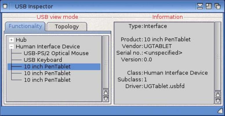
Next step was to rename the driver to UGTablet.usbfd (based on the name the tablet announces to the USB system and so I presume the underlying chipset) and create a new UGTablet.fdclass file using the vendor ID of the XP-Pen tablet.
FUNCTIONDRIVER
NAME      "UG Tablet Driver"
VENDOR     0x28BD
TYPE      INTERFACE
PRI       6
DRIVER    "UGTablet.usbfd"
Having installed those I plugged in the tablet to see what would happen...
Success! Of a very limited kind, the tablet was detected and the driver took over the USB endpoints but nothing more happened. At least it didn't crash!
So onto the process of working out why the tablet was attaching but not working... First step was to add some serial debug lines that could tell me which sections of code were being executed. Something like this
um->IExec->DebugPrintF("%08lx: %s %ld\n", um->IExec->FindTask(NULL), __FUNCTION__, __LINE);
"um->" because my code was keeping a local copy of the required library interfaces in the usbtablet structure. I added the FindTask() as I could see from USBInspector that the tablet was showing up as three separate endpoints (unlike the UCLogic that showed up as only 1). Two of these showed as bootclass (subclass 1) and the third didn't.
Each of those endpoints would get handled on their own Process, so I would need to be able to distinguish which debug came from which process. I ran the test driver on my X1000 and captured the debug data on my SAM-Flex via a serial cable and using the program "Termie". A basic but usable terminal emulator.
The USB interface driver essentially works by sending an IORequest, waiting for the reply, processing the data and then sending another request, looping utill done. With the debug in place I could quickly see that the driver was receiving the expected flow of IORequest responses whenever I brought the stylus close to the tablet, but than the meat of the processing code was being skipped. The handler function looked something like so:
VOID MouseHandler( struct usbtablet *um )
{
struct USBIOReq *req;
int16 X, Y,P;
int16 But1 = 0, But2 = 0;
int16 tmp1, tmp2;
int16 code, qual;

    req = (struct USBIOReq *)um->IExec->GetMsg( um->UsbMP );
    if ( req )
    {
        if ( req->io_Error == USBERR_NOERROR )
        {
          ----8<-----
          main processing code goes here
          ----8<-----
        }

	 /* Send USB  Next Request */

	 um->UsbIOReq->io_Command    = CMD_READ;
	 um->UsbIOReq->io_Data       = &um->UsbData;
	 um->UsbIOReq->io_Length     = sizeof( struct UGTabletData );
	 um->UsbIOReq->io_EndPoint   = um->UsbStatusEndPoint;


	if ( um->UsbIOReq->io_Length > LE_WORD( um->UsbEndPointDscrIn->ed_MaxPacketSize ))
	{
	     um->UsbIOReq->io_Length = LE_WORD( um->UsbEndPointDscrIn->ed_MaxPacketSize );
	}

	 m->IExec->SendIO( (struct IORequest *)um->UsbIOReq );

    }
}
It's called MouseHandler() as the original code was an example of BootMouse driver, writen by René Olsen, and I never changed the function names!
Adding another line of debug revealed that req->io_Error was set to -36, which after cross referencing with the usb includes gave USBERR_BUFFEROVERFLOW. The notes in the usb/system.h include file for this error number were as follows:
READ returned more data than would fit into buffer.
It's up to you to decide if this should be treated
as an error (not all data the USB EndPoint wanted to
return could be stored and delivered to you), or as a
success (you actually got the amount of data you
requested from the USB EndPoint. It's right there in
your buffer waiting for you) */
This suggested that I should at least be getting partial information from the IORequest so I changed the condition to
if ( req->io_Error == USBERR_NOERROR || req->io_Error == USBERR_BUFFEROVERFLOW)
and retested. As soon as the stylus came in range of the tablet the mouse pointer was clamped to the top let corner (coordinates 0,0) the stylus tip did not work as the left mouse button (LMB), nor did the other stylus buttons work. It seems, in the case of this tablet at least, that a buffer overflow resulted in no data being transfered.
The tablet buttons (as opposed to the stylus buttons) did produce some data however, although at this point the data was being misinterpreted as stylus data and so just making small movements in the mouse position. This suggested that the data packets from two srcs were different sizes.
The length of data returned should be indicated by the um->UsbEndPointDscrIn->ed_MaxPacketSize field, but when I add debug to check how large these values were in both cases they were much larger than the expected data. So I temporarily modified the code to pass a dynamic buffer of the full MaxPacketSize and checked the value of req->io_Actual, to see how much data was returned. The values were 8 bytes for the tablet buttons and 10 bytes for the stylus data. The original UGTabletData structure (inherited from my previous UCLogic Driver as a starting point) was:
struct UGTabletData {
    uint8     mode;
    uint8     Buttons;
    uint16    X;        /* Little Endian X coord  */
    uint16    Y;        /* Little Endian Y coord  */
    uint16    Pressure; /* Little Endian Pressure */
};
This is only 8 bytes long, hence the buffer overun error. As a first step then I simply added a uint16 dummy to the end of the structure makeing it's size 10 bytes.
Removing the temporary buffer and reverting to writing inot the struct UGTabletData and I was rewarded with my first tangible success. The mouse pointer now tracked the stylus position and the stylus tip worked as the LMB!
Next step was to fire up SketchBlock and see how the tablet performed. I quickly saw that stylus movement worked as expected, if significantly smoother than my old UCLogic tablet, but the pressure values were clearly off, increasing quickly with stylus pressure but then dropping to '0'. Checking the documentation for the tablet I found the pressure resolution was much higher 8192 steps as opposed to UCLogics 1023. A simple fix here, simply changing the value of the DEFAULT_RANGE_P constant in the driver to 8096.
So now to determine what that extra 2 bytes of data were representing. I added a line of debug to dump out the values returned to serial. Initially treating it as a little endian 16bit value. Then simply played arround with the stylus and watched what came out looking for patterns. Intially I looked like it might be pressure related, this was confusing why would the pressure be encoded twice? Then I realised I was dumping the wrong fields, so the debug I was seeing was a combination of the pressureand the unknown field. Once I fixed up that, so I was only looking the data I was interested in I saw that it was clearly related to the tilt of the stylus. The numbers being output were not obvious though, at least not at first. I took a look at the specifications at www.usb.org/hid ( a document that seems treated as not so much a code as a guideline ) to see if I could find any clues. It seamed I should be getting separate X and Y data, but no guide as to exactly how it should be encoded.
So I very carefuly tested by tilting strictly in the X axis or the Y axis and after a while realised I was getting two signed bytes of data, one for each axis. Adjusting the debug output to suit this I could see that I was getting values that varied from -60 to 60 in each axis with 0,0 being vertical. In fact the values seemed to match the inclination in degrees. Very helpful.
With that information I modified my struct UGTabletData:
struct UGTabletData {
    uint8     mode;
    uint8     Buttons;
    uint16    X;        /* Little Endian X coord  */
    uint16    Y;        /* Little Endian Y coord  */
    uint16    Pressure; /* Little Endian Pressure */
    int8        TiltX;
    int8        TiltY;
};
The next dilemma was to pass on this data to the Amiga operating system. Tilt data is passed via tags TABLETA_AngleX and TABLETA_AngleY in the IESUBCLASS_NEWTABLET IntuiEvent structure. However the correct encoding wasn't completely obvious. The value needed to be normalised into a signed LONG word (ie a int32) but how this was to be normalised was not clear. There is also a TABLETA_AngleZ which doesn't quite apply to conventional tablets (though could perhaps represent stylus twist?). I put some thought into this myself, then confered with Alaxandre Balaban (author of the wacom driver) and asked on the os4beta mailing list for input. It seems the problem is no software has yet used this feature so there is lack of precendent in how to interpret this. Should the range to normalise over be:
- The full range of the tablet - in this case +- 60
- the full practical range - one might think the stylus can only tilt by 90° in any directon
- One full rotation in each direction so that 0x7FFFFFFF = 360 and 0x80000000 = -360
In the end the code to convert looked like:
um->IENT_Tags[1].ti_Tag = TABLETA_AngleX;
um->IENT_Tags[1].ti_Data = -( um->UsbData.tablet.TiltY) * (0x7fffffff / 360);

um->IENT_Tags[2].ti_Tag = TABLETA_AngleY;
um->IENT_Tags[2].ti_Data = -( um->UsbData.tablet.TiltX) * (0x7fffffff / 360);
I added a few lines of debug to SketchBlock to confirm tilt data was being passed thoigh sanely and it was, wahooo!
So the stylus was now fully working. It would be rewally great to get the 8 buttons on the tablet working too. These were handled by a seprate endpoint, but as noted above there as no way to tell which of the two bootclass endpoints was which. Studying the data though I realised that the mode byte was 7 for stylus data and 6 for tablet button data. That made it very easy to distinguish between the two datastreams, but only once they had started returning data.
I setup another line of serial debug to print out the button data as an 8 byte hex number and watched how it changed as I pressed various combinations of buttons. I could see that as I pressed more buttons the values generated shifted right down the 8byte sequence, mostly starting from the third byte. As buttons were released the data from the remaining buttons shifted left back towards the started of the 8byte sequence. So some kind of buffer allowing up to 6 buttons to be pressed at a time. The second byte was also taking on different values that didn't seem to shift down the pipeline.
I remembered that when plugged into my linux laptop the buttons had worked like a very limited keyboard, with an odd choice of keys so I took a look at Rene Olsens example rKeyboard driver on os4depot.net. The keyboard equivalent of the code I started the UCLogic driver from.
I saw the data structure returned by the boot keyboard was almost identical to the tablet keys, just that the Modifier field was moved one byte down and the first byte reused to determine the datatype. So:
/* Boot key board */
struct USBBootkbdData {
    uint8   Modifier;
    uint8   reserved;
    uint8   Keycode[6];
};

/* Tablet data */
struct UGTabletData {
    uint8     mode;
    uint8     Modifiers;
    uint8 Keycode[USBKBD_KEYCODEFIELDS];
};
As the data was being written into the same buffer be it tablet button or stylus I combined the two structures using a union. I could then test the mode value, handle value 7 as a stylus and value 6 as a button. No other values have shown up so far....
struct UGTabletData {
    uint8     mode;
    uint8     Buttons;
    union {
        struct {
            uint16    X;        /* Little Endian X coord */
            uint16    Y;        /* Little Endian Y coord */
    	    uint16    Pressure;
	    int8     TiltX;
	    int8     TiltY;
        } tablet;
        struct {
            uint8 Keycode[USBKBD_KEYCODEFIELDS];
            uint16 pad;
        } buttons;
    };
};
I could adapt the code from the rKeyboard driver to process the keycode buffer and generate the input.device RawKey events required.
By default the buttons mapped to a strange mix of characters including "b" "e" "i" "+" -" and a few that were unprintable, so I decided it would be more useful to map them to the first 8 functions keys by default. Later I intend to add some configuartion to the GUI.
The GUI itself was the last main issue to deal with. In the UCLogic driver it's created when the driver Process is created and it's controled by a unique commodity, however in the UGTablet case there are two / three processes, to the first created the commodity and GUI the second caused it to immediatly pop up. This was not ideal as really the GUI shouldn't appear till the user presses CTRL ALT U. Also the GUI needed to be controlled by the process handling the stylus messages and this couldn't be guaranteed as I didn't know which process was which till after I'd started the commodity.
The solution then was to only create the commodity if it didn't exist, move the creation point to the Handler function rather than the Setup function, and also just in case not require success. This gets the GUI working, but has some down sides. The GUI can only be effectively used by the first tablet attached (though I'm not sure many will use multiple tablets, you ought to be able to in principle, just as you can use multiple mice and keyboards). The commoddity does not become "live" till after the stylus triggers an event so you must touch the tablet to enable the GUI. Some space for improvement here, but it does do the main job of allow the tablet to be configured.
Adding Tilt Support To SketchBlock
Having added tilt support to the driver, I naturally wanted to make ue of it in SketchBlock. First step was to add it to the internal SketchBlock API. SketchBlock works in floating point so I needed to map the normalised signed integer discussed about to a floating point value from 1.0 (360 °) to -1.0. (-360 °) As I knew that the useful range of that might only be +- 90 ° I added a setting to define the useful tilt range. Defaulting to 0.25. The combination of the above results in:
LONG tx = IUtility->GetTagData(TABLETA_AngleX ,0,td->td_TagList);
LONG ty = IUtility->GetTagData(TABLETA_AngleY ,0,td->td_TagList);

App->ap_TiltX =  (float)(((double)tx)/ 2147483648.0);
/* clamp and normalise to the userdefined tilt range */
if(App->ap_TiltXRange != 0.0)
{
    if(App->ap_TiltX > App->ap_TiltXRange)
    {
        App->ap_TiltX = App->ap_TiltXRange;
    }
    App->ap_TiltX = App->ap_TiltX / App->ap_TiltXRange;
}

App->ap_TiltY =  (float)(((double)ty)/ 2147483648.0);
/* clamp and normalise to the userdefined tilt range */
if(App->ap_TiltYRange != 0.0)
{
    if(App->ap_TiltY > App->ap_TiltYRange)
    {
        App->ap_TiltY = App->ap_TiltYRange;
    }
    App->ap_TiltY = App->ap_TiltY / App->ap_TiltYRange;
}
The next step was to add functions to the plugin API to allow plugins to access the tilt value. SketchBlock exports an API to the plugins that is quite like a AmigaOS4 library interface, these functions allow the plugins to access the global data without needing to have direct access or knowledge of how that data is stored. I originally planned to make this public, so that third party devs could write their own plugins, but the practicalities of writing the required documentation and maintaining compatabilty meant this idea fell by the wayside. I'm not sure the 'market' is big enough for third party plugins anyway these days.
Next I added scaling of the brush with tilt in an 'always on' fasion just to test out the concept. I used the simple algorthm of multiplying the size by 1.0 / (1.0 - fabsf(tilt)) . This gave quite dramatic scaling as the tilt increased, too much in practice, as the tilt approach 1.0 the denominator approached 0.0!. The scaling in the X and Y axes were indpendent, which made for interesting effects with varying brush shape. What would have been really nice would have been to scaling along the angle defined by the X and Y tilt comonent, ie in the direction of the combined tilt, but this would require a big rewrite of my highly optimised brush stamping code. Something I really didn't want to take on at this point.
Having got the proof of concept working I added an option to the paint to to enable tilt support and add options similar to the new pressure range settings introduced in SketchBlock 3.3. The algorthom for calculating tilt scaling then become the more complex:
if(sbd->sd_PressureFlags & TILT_SIZE)
{
    rw = rw * (1.0 + sbd->sd_TiltSizeRange.pr_Factor * fabsf(sbd->sd_TiltX)) / sbd->sd_TiltSizeRange.pr_Divisor;
    rh = rh * (1.0 + sbd->sd_TiltSizeRange.pr_Factor * fabsf(sbd->sd_TiltY)) / sbd->sd_TiltSizeRange.pr_Divisor;
}
I reused some of the spare bits in the PressureFlags field rather than add another, so maybe that field ought to be renamed DynamicsFlags or some such, but that's job for a later code cleanup. It's internal code anyway so doesn't entirely matter. I know what I mean :-).
Having added tilt scaling, and to be honest found it difficult to work with at first, I decided that changing colour with tilt might also be nice and was quite easy to implement. Currently the direct of tilt is ignored and the colour varies between just two colours (foreground and background as displayed in the tools window), a future improvement might make it vary betwwn 4 colours one for each corner of the X / Y tilt range.
As a final feature for this stage of development I added an option to switch the X and Y tilt values, so that scale in particular could produce agreater range of brush strokes.
The paint tool settings with tilt support now look like so.

And here is a quick example of tilt size and colour. Tilt seams to make writing feel a little more natural, but still needs alittle practice to get used to writing with a tablet.

So I hope you found this description of my development process whilst writing both the driver and the sketchblock extension interesting. The new driver is available on os4depot and the updated version of SketchBlock will be available on AmiStore soon as part of the SketchBlock Pro 3.4 feature set.